Description
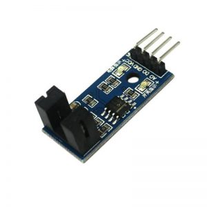
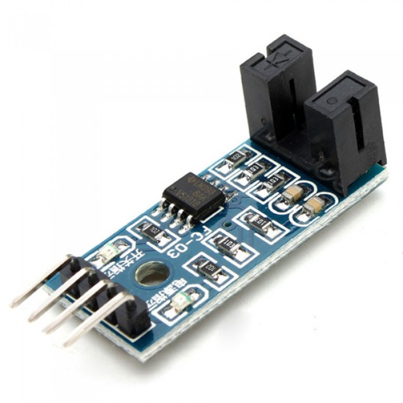
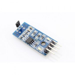
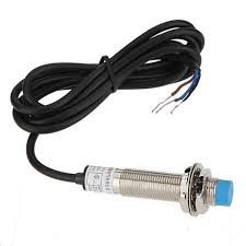
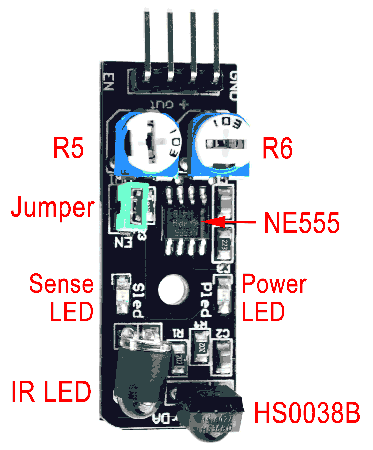
This sensor is known variously as the Keyes, KeyesIR or Keyestudio KY-032. It is the the functional equivalent of the IrBeady IR-08H, also known as the AD-032. The sensor uses a four pin connector, The pins are labeled: EN (Enable), out (Output), + (Power) and GND (Ground). There are also two potentiometers on the board and one jumper (see picture).
Manufacturer’s Specifications:
- Working voltage: 3.3V to 5VDC
- Working current: ≥ 20mA
- Operating temperature: -10°C to +50°C
- Detection distance: 2 to 40cm
- IO Interface: 4-pin (EN / +V / S / GND)
- Output signal: TTL level
- LOW level if obstacle detected
- HIGH if no obstacle detected
- Adjustment: two single-turn variable resistors
- Effective angle: ±35°
- Size: 28mm × 23mm
- Weight: 9g
From the HS0038BD data sheet:
These products are designed to suppress spurious output pulses due to noise or disturbance signals. Data and disturbance signals can be distinguished by the devices according to:- carrier frequency,
- burst length and
- envelope duty cycle.
- DC light (e.g. from tungsten bulb or sunlight)
- Continuous signals at any frequency
- Strongly or weakly modulated noise from fluorescent lamps with electronic ballasts.
Sample C++ code to strobe the IR LED with a 600µs pulse and test for a return:
digitalWrite( enablePin, HIGH); // Enable the internal 38kHz signal.
microDelay( 210); // Wait 210µs (8 pulses of 38kHz).
if( digitalRead( outputPin)) // If detector Output is HIGH,
{
objectDetect = false; // then no object was detected;
}
else // but if the Output is LOW,
{
microDelay( 395); // wait for another 15 pulses.
if( digitalRead( outputPin)) // If the Output is now HIGH,
{ // then first Read was noise
objectDetect = false; // and no object was detected;
}
else // but if the Output is still LOW,
{
objectDetect = true; // then an object was truly detected.
}
}
digitalWrite( enablePin, LOW); // Disable the internal 38kHz signal.
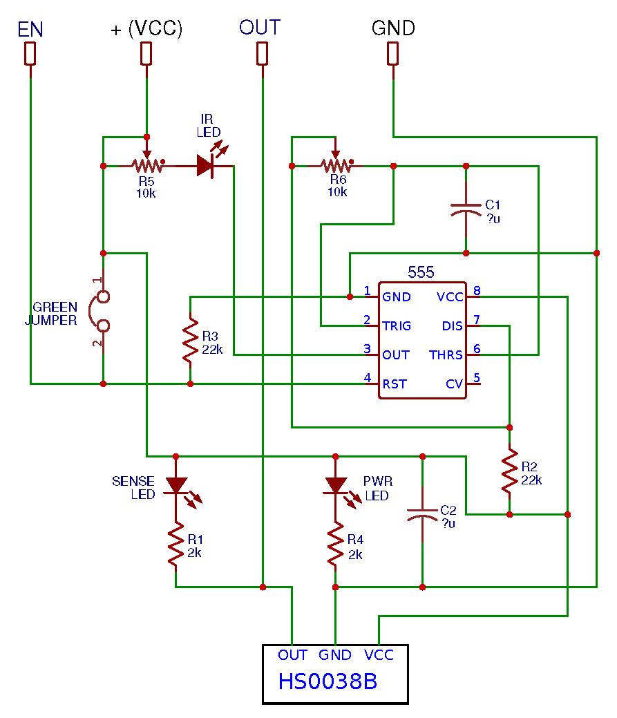
This schematic of the KY-032 was created by examining the circuit board. This is my second attempt. I cannot guarantee its accuracy. It was drawn using the EasyEDA online electronic circuit design tool. The values of the two capacitors are not known.
I want to thank Arik Yavilevich for his valuable contribution. Further comments and corrections will be appreciated.